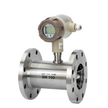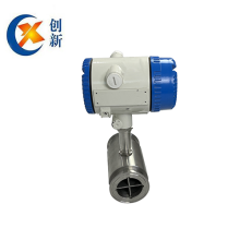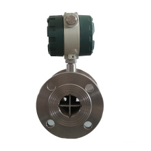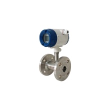


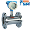
LWGY Medidor de flujo de agua digital de turbina líquida
Información básica
Modelo: LWGY Series
Descripción del producto
Para líquidos (agua, diesel, gasolina)
Alta Precisión: 1.0% o 0.5% o tasa
DN4 a DN200
LWGY Medidor de flujo de agua digital de turbina líquida
PRESUPUESTO
Actuación
Repetibilidad: ± 0,2%
Precisión: Estándar: ± 1% de la lectura Opcional: ± 0,5% de la lectura
Componentes húmedos
Carcasa: Estándar - Acero inoxidable 304 Opcional - Acero inoxidable 316
Rodamientos y Eje: Carburo de Tungsteno
Rotor: Estándar - 2Cr13 Acero inoxidable
(Aleación opcional CD4Mcu)
Anillos de retención: acero inoxidable 316
Señal de salida: (donde corresponda)
Sensor: Señal del pulso (nivel bajo: ≤0.8V; Alto nivel: ≥8V)
Transmisor: Señal de corriente CC de 4 a 20 mA Señal Distancia de transmisión: ≤1,000 m
Conexiones eléctricas: Básicas Tipo: Conector Hausman o cable de tres núcleos
A prueba de explosión Tipo: ISO M20 × 1.5 Mujer
Nivel de Prueba de Explosión:
Estándar: Ninguno
Opcional: ExdIIBT6
Nivel de protección: IP65
CONDICIONES DE FUNCIONAMIENTO
Ambiente:
Temperatura: -10 ° C a + 55 ° C
Presión: 86 a 106 KPa
Humedad relativa: 5% a 90%
Fuente de alimentación:
Sensor: + 12V DC (Opcional: + 24V DC)
Transmisor: + 24V DC
Visualización de campo Tipo B:
Batería de litio integral de 3.2V (otros disponibles bajo petición)
Visualización de campo Tipo C:
+ 24V DC
Temperatura y presión del líquido:
Temperatura:
-20 ° C a + 110 ° C
Presión:
La presión del líquido debe limitarse según la clasificación.
Hoja de datos para opcional:
|
|
|
|
|
Description |
||||
Type |
A |
|
|
|
|
Flow sensor pulse output three-wire system, +12V power supply; |
|||
B |
|
|
|
|
Local display, powered by 3.6V battery; |
||||
C |
|
|
|
|
Local display with 4~20mA or pulse output, powered by 24V; |
||||
D |
|
|
|
|
Flow transmitter 4~20mA output, powered by ,24V; |
||||
Nominal drift diameter |
4 |
|
|
|
Normal flow range m3/h |
0.04~0.25 |
Extended flow range m3/h |
0.04~0.4 |
|
6 |
|
|
|
0.1~0.6 |
0.06~0.6 |
||||
10 |
|
|
|
0.2~1.2 |
0.15~1.5 |
||||
15 |
|
|
|
0.6~6 |
0.4~8 |
||||
20 |
|
|
|
0.8~8 |
0.45~9 |
||||
25 |
|
|
|
1~10 |
0.5~10 |
||||
32 |
|
|
|
1.5~15 |
0.75~15 |
||||
40 |
|
|
|
2~20 |
1~20 |
||||
50 |
|
|
|
4~40 |
2~40 |
||||
65 |
|
|
|
7~70 |
3.5~70 |
||||
80 |
|
|
|
10~100 |
5~100 |
||||
100 |
|
|
|
20~200 |
10~200 |
||||
125 |
|
|
|
25~250 |
12.5~250 |
||||
150 |
|
|
|
30~300 |
15~300 |
||||
200 |
|
|
|
80~800 |
40~800 |
||||
Explosion protection |
|
|
|
Not marked, without explosion protection |
|||||
B |
|
|
Explosion protection type |
||||||
Precision class |
A |
|
Precision: Class 0.5 |
||||||
B |
|
Precision: Class 1.0 |
|||||||
Turbine type |
A |
Normal flow range |
|||||||
B |
Extended flow range |
||||||||
|
Note: Sensors with pipe diameter of DN4~DN40 are of thread connections with maximum operating pressure of 6.3Mpa. Sensors with pipe diameter of DN50~DN200 are of flange connections with maximum operating pressure of 2.5Mpa. Sensors with pipe diameter of DN4~DN10 are provided with front and rear straight pipe sections and filters. Please specify when placing an order if flange connections are required for pipe diameter of DN15~DN40. Please specify when placing an order for high pressure type and special requirements. | |||||||||


Grupos de Producto : Medidor de flujo de turbina
Premium Related Products